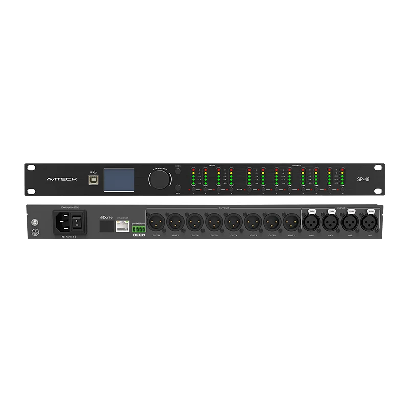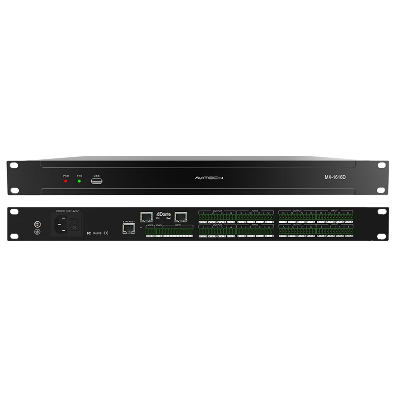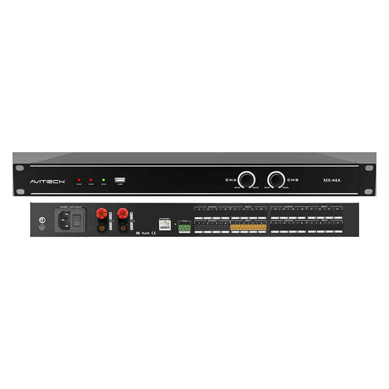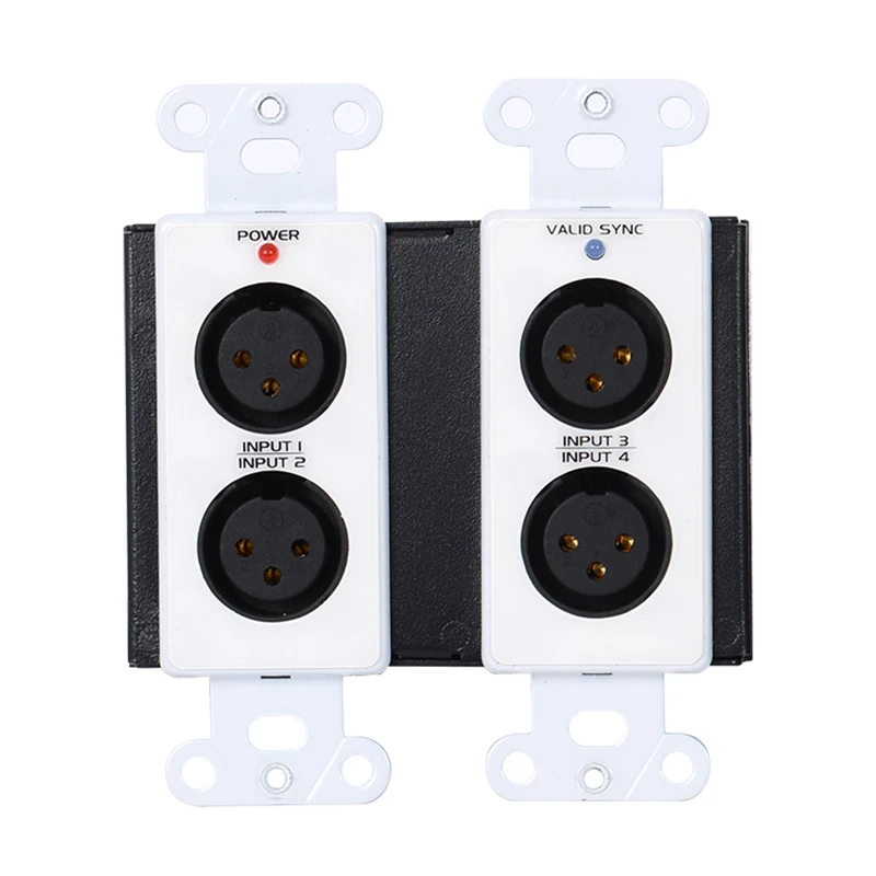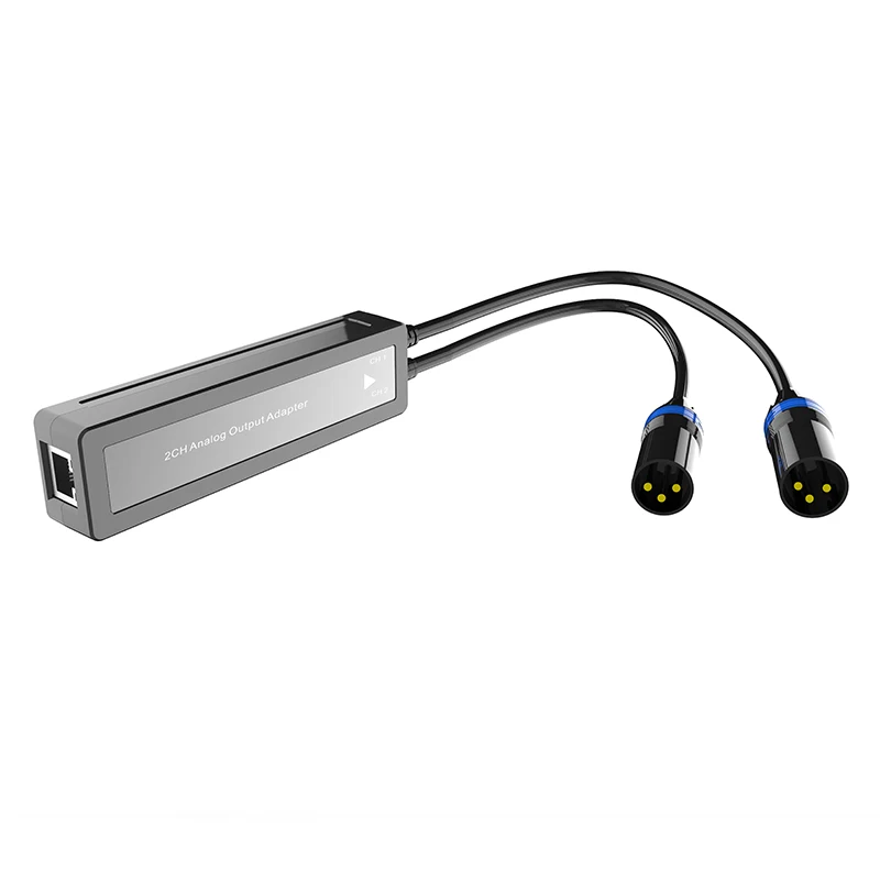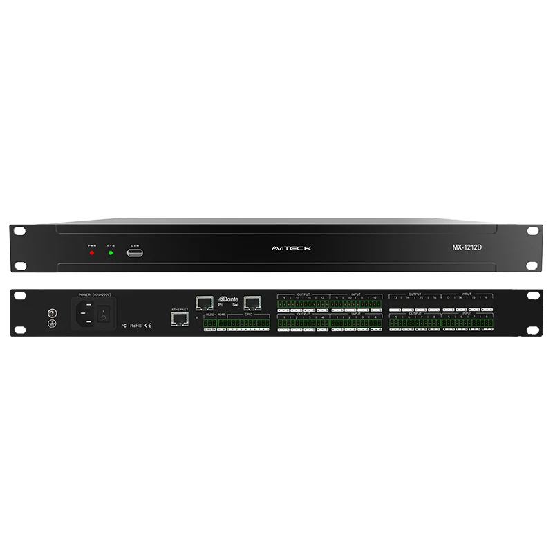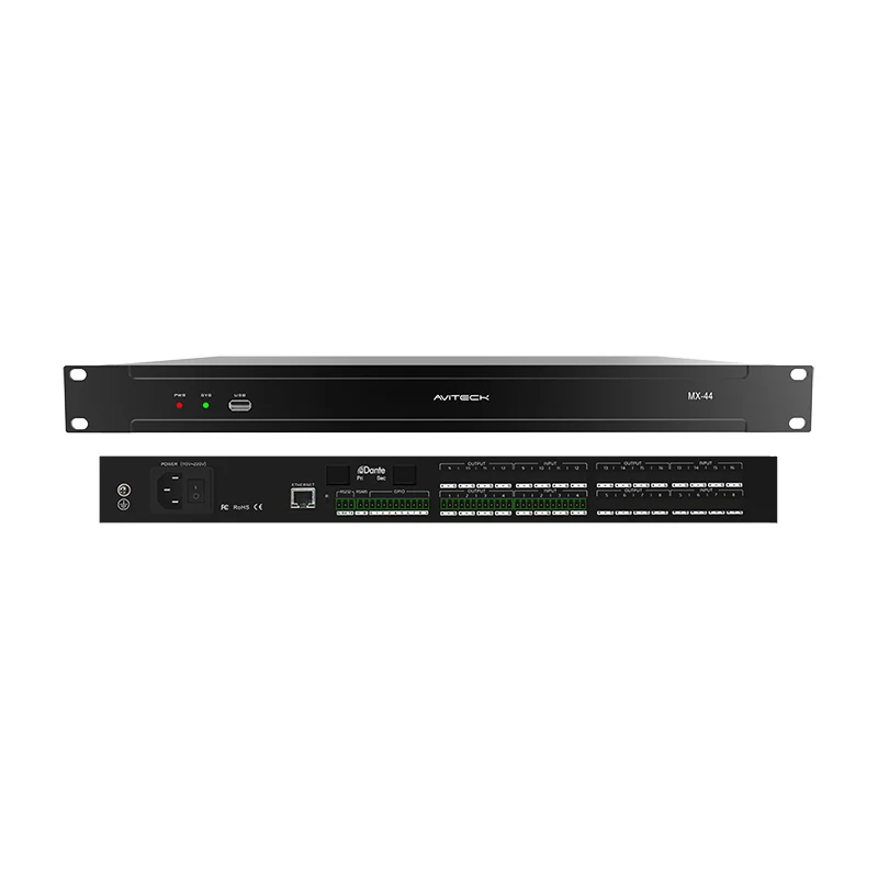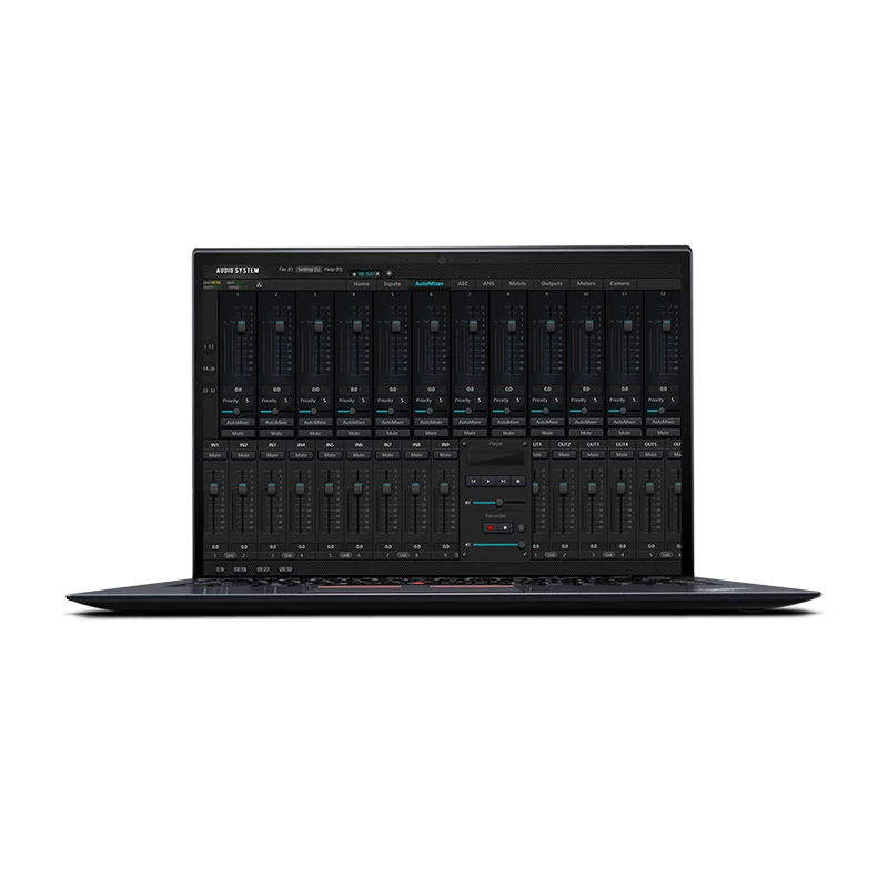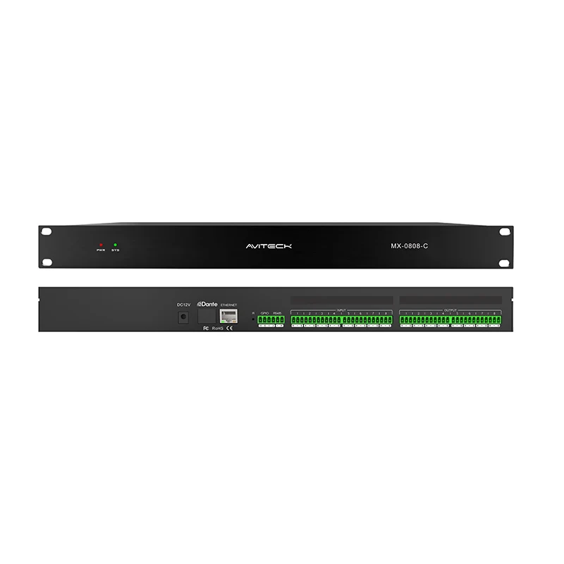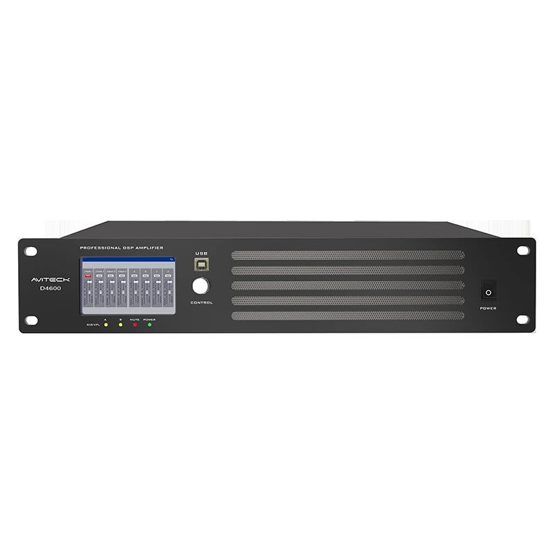

A digital audio matrix system routes audio from multiple inputs to selected outputs, allowing different audio sources to serve different zones or loudspeaker groups. Depending on the model, the system may also provide digital signal processing (DSP), such as equalization, delay, crossover filtering, and limiting. These functions make matrix systems useful in conference rooms, education facilities, hospitality venues, commercial buildings, and other installed-audio applications.
Although the control interface and available functions vary by product, the basic workflow is similar: check the signal path, configure routing, set appropriate levels, apply only the processing required, save the configuration, and verify the complete system. Always refer to the user manual for the specific model before changing settings.
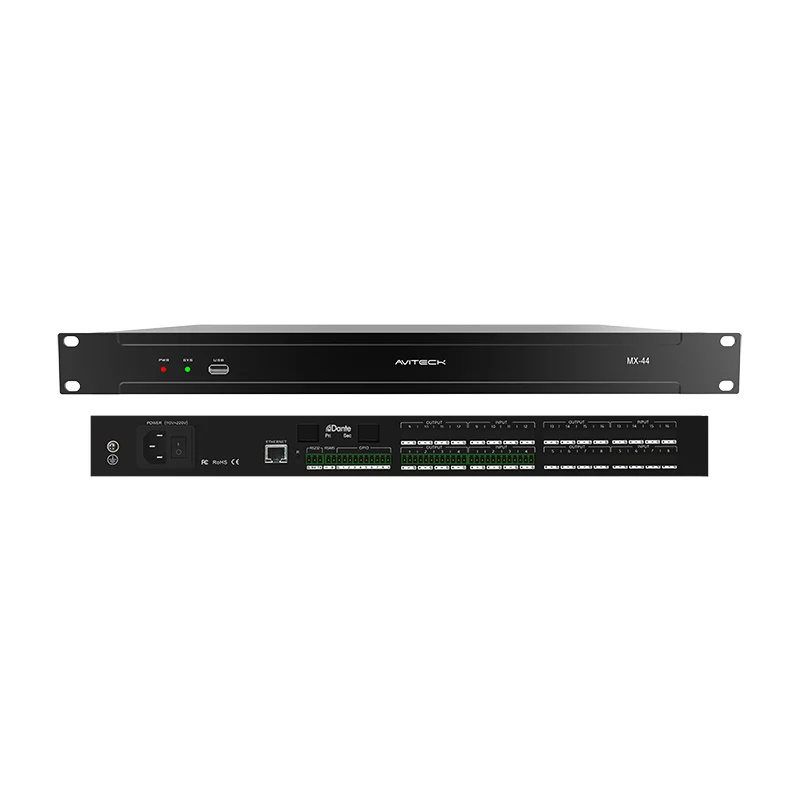
Before opening the control software, identify the system’s inputs, outputs, connected equipment, and intended audio zones. Inputs may include microphones, media players, computers, or audio received over a network. Outputs may feed power amplifiers, active loudspeakers, recording devices, or other audio systems.
A typical signal path is: Audio Source → Matrix Input → Routing / Mixing → Output Processing → Amplifier or Active Loudspeaker. The exact order and available processing blocks depend on the device.
Before making changes, confirm which physical or network input corresponds to each source and which output feeds each destination. Clear channel labels reduce routing mistakes during setup and future maintenance.
Complete these checks before configuring the system:
· Confirm that the matrix, amplifiers, sources, and network connections are installed as intended.
· Check power, cabling, and network status where applicable.
· Open the control software or web interface specified by the product manual.
· Connect to the correct device and confirm that the displayed device or channel information is consistent with the installation.
· Rename inputs and outputs with practical labels, such as “Lectern Mic,” “PC Audio,” “Room A,” or “Lobby Speakers,” if the interface supports channel naming.
Do not assume that every matrix uses the same software layout, connection method, or menu names. Follow the instructions for the exact model and firmware version.
Matrix routing determines which input signals are sent to which outputs. A single source may need to reach several zones, while other sources may need to remain isolated to a specific room or destination.
1. Open the matrix or routing view in the device’s control interface.
2. Identify the required input and output channels using the labels prepared during setup.
3. Assign each source to the intended destination according to the system design.
4. Check any available crosspoint level, send level, or routing enable control before enabling the path.
5. Test each route with a known audio source at a low, safe level, and confirm that sound reaches only the intended destinations.
If audio appears at the wrong loudspeaker or in the wrong zone, recheck the routing assignments and channel labels before changing equalization or other DSP parameters.
Correct gain structure helps maintain a clear signal while reducing the risk of noise, distortion, or clipping. Start with conservative levels and increase them gradually while monitoring signal indicators and listening at a suitable volume.
Set the source or input gain so that normal program material produces a healthy signal without persistent overload indications. Microphone and line-level sources may require different input settings; use the source specification and the device manual as references.
Set output levels to suit the connected equipment and intended listening area. Check the output level, any downstream amplifier input setting, and the amplifier’s own controls together. Avoid compensating for a routing or connection problem by simply raising the output gain.
If the system is silent, check mute status, routing, source playback, input signal presence, output level, and downstream equipment in that order.
Many digital audio matrix systems include digital signal processing (DSP). Available tools differ by model, so only use functions confirmed in the product documentation.
Input processing may be used to adjust source level or tone and, on supported models, to apply other source-side functions. Make changes in small steps and compare the result with the original signal.
Output processing is commonly used to tailor the signal for a specific loudspeaker or listening zone. Depending on the device, this may include equalization (EQ), delay, crossover filters, polarity, gain, or a limiter.
· Equalization: correct obvious tonal issues and follow loudspeaker or room-design guidance; avoid large boosts without a clear reason.
· Delay: use when timing alignment is required between loudspeakers or zones, and verify the result by listening or measurement.
· Crossover: use settings appropriate to the loudspeaker system and amplifier arrangement; incorrect crossover settings can reduce performance or risk damage.
· Limiter: configure according to the system design and equipment requirements. Do not assume that every model offers the same limiter controls.
· Feedback: reduce unnecessary microphone gain, review microphone and loudspeaker placement, and use supported processing only as part of a wider feedback-control approach.
Avoid changing several DSP parameters at once. Adjust one function, listen or measure the result, and document the change before moving to the next.
If the system supports scene or preset storage, save a verified configuration so it can be recalled after a restart or adapted for another operating mode. Preset behavior and storage options vary by product.
6. Finish and verify the routing, levels, and processing for the intended use case.
7. Save the configuration using a clear name, such as “Standard Meeting” or “Presentation Mode,” if naming is supported.
8. If the device allows multiple presets, document the purpose of each one and who is authorized to modify it.
9. Recall the saved preset and confirm that routing, levels, and processing behave as expected.
10. Keep a record of important settings and maintain a backup where the software or device supports it.
Do not overwrite a known-good configuration until the replacement has been checked. If preset loading behaves unexpectedly, consult the model’s manual to confirm what parameters are stored and recalled.
After configuration, test the full signal path from each source to each intended destination. Use a checklist to ensure that the system is ready for normal operation.
|
Check |
What to confirm |
|
Input signal |
Each source is connected and produces a stable signal. |
|
Routing |
Each source reaches the intended output or zone. |
|
Levels |
Normal operating levels are clear and do not show persistent clipping. |
|
DSP settings |
Processing matches the loudspeaker and application requirements. |
|
Mute and control |
Mute, volume, and other user controls work as expected. |
|
Presets |
Saved configurations can be recalled and have been verified. |
|
Documentation |
Channel labels and the final configuration are recorded. |
No audio output: Check source playback, input signal, routing assignments, mute status, output level, cabling, and downstream amplifier or loudspeaker power.
Audio reaches the wrong zone: Check the matrix crosspoints and input/output labels. Confirm the physical connections against the installation plan.
Distorted or clipped sound: Reduce excessive source, input, output, or amplifier gain. Check signal indicators at each stage rather than lowering only the final output.
Acoustic feedback: Review microphone placement, loudspeaker direction, microphone gain, and room acoustics. Use EQ or other supported tools carefully; processing alone may not solve the underlying cause.
Control software cannot connect: Verify the selected device, network connection, IP configuration where applicable, and any access requirements described in the manual.
Preset does not restore the expected setup: Check whether the selected preset was saved correctly and which parameters the model stores. Compare with the documented baseline configuration.
For repeatable results, follow the same sequence whenever commissioning a new system or making a significant configuration change:
11. Review the system design and identify all inputs and outputs.
12. Confirm device connectivity and label channels.
13. Configure and test matrix routing.
14. Set input and output levels.
15. Apply only the DSP processing required by the application.
16. Save a clearly named preset if supported.
17. Run a complete source-to-destination test and document the final settings.
A matrix focuses on routing multiple inputs to multiple outputs. Depending on its design, it may also provide mixing and DSP functions. A conventional mixer is generally organized around channel mixing and a mix-bus workflow, although modern products can overlap in functionality.
Not necessarily. Many devices retain settings or provide preset recall, but startup behavior and memory functions depend on the specific model. Check the manual and test the expected power-cycle behavior during commissioning.
Many matrix systems support routing one source to more than one output. Confirm the available routing options and any level controls on the selected model.
A matrix may offer processing that helps manage audio, but feedback control also depends on microphone and loudspeaker placement, gain structure, room acoustics, and system design. Do not assume that a matrix automatically eliminates feedback.
No. The core workflow is similar, but supported inputs, processing functions, control software, preset behavior, and parameter ranges vary by model. Always use the documentation for the exact device.
Explore FHB Audio digital audio matrix products for system designs that require flexible input-to-output routing and centralized audio control. Depending on the project, related topics may include DSP input and output processing, conference room audio systems, and networked audio integration.
Choosing the right matrix system and configuring it correctly starts with understanding the number and type of audio sources, output zones, control requirements, and processing needs. Contact Shenzhen FHB Audio to discuss your application and identify a suitable solution.